DC Motor
ContinuousThe DCMotor block models an electromechanical permanent-magnet direct-current motor plant. It captures the dynamic interaction between electrical armature dynamics and mechanical rotor torque balance across 1st, 2nd, and 3rd order modes.
Real-World Analog: Represents standard brushed or brushless DC motors found in robotic joints, electric vehicle wheel drives, drone gimbals, conveyor rollers, and computer cooling fans.
Video tutorial
Mathematical Model
The motor is governed by Kirchhoff's voltage law and Newton-Euler rotor dynamics:
Inputs & Outputs
| Direction | ID | Label | Type | Status |
|---|---|---|---|---|
| → In | voltage |
Voltage (Va) | number | Optional |
| → In | loadTorque |
Load Torque (TL) | number | Optional |
| → In | p |
+ | number | Optional |
| → In | n |
- | number | Optional |
| → In | flange_a |
Shaft | number | Optional |
| → In | flange_b |
Case | number | Optional |
| → In | H |
H | number | Optional |
| ← Out | speed |
Speed (ω) | number | Output |
| ← Out | current |
Current (ia) | number | Output |
| ← Out | torque |
Torque (Te) | number | Output |
| ← Out | position |
Position (θ) | number | Output |
Parameters
| Parameters | Label | Type | Default | Description |
|---|---|---|---|---|
preset |
Motor Preset | select | custom |
Select a pre-calibrated physical motor model or configure custom parameters |
dynamicsMode |
Model Dynamics | select | secondOrder |
Select dynamical model order and complexity |
resistance |
Resistance (R) | number | 1 |
Armature winding resistance [Ω] |
inductance |
Inductance (L) | number | 0.5 |
Armature winding inductance [H] |
torqueConstant |
Torque Constant (Kt) | number | 0.1 |
Motor torque constant [N·m/A] |
backEmfConstant |
Back-EMF Constant (Ke) | number | 0.1 |
Back-EMF constant [V/(rad/s)] |
inertia |
Rotor Inertia (J) | number | 0.02 |
Rotor moment of inertia [kg·m²] |
damping |
Viscous Friction (b) | number | 0.05 |
Viscous damping coefficient [N·m·s/rad] |
brushDrop |
Brush Voltage Drop (Vbrush) | number | 0 |
Total contact voltage drop across carbon brushes [V]. Sets effective voltage to 0 when |Va| <= Vbrush. |
currentLimit |
Current Limit (Imax) | number | 0 |
Armature peak current limit [A]. Clamps armature current to ±Imax. 0 = unlimited. |
coulombFriction |
Coulomb Friction / Stiction (Tc) | number | 0 |
Breakaway Coulomb friction torque opposing motion [N·m]. Prevents rotation until net torque exceeds Tc. |
initialSpeed |
Initial Speed (ω0) | number | 0 |
Initial angular velocity at t=0 [rad/s] |
initialCurrent |
Initial Current (ia0) | number | 0 |
Initial armature current at t=0 [A] |
initialPosition |
Initial Position (θ0) | number | 0 |
Initial rotor position at t=0 [rad] |
coggingTorque |
Cogging Torque (Tcog) | number | 0 |
Peak reluctance cogging torque amplitude due to stator slotting [N·m]. 0 = neglected. |
coggingSlots |
Cogging Slots / Poles | number | 12 |
Number of cogging torque periods per mechanical revolution. |
Usage Examples
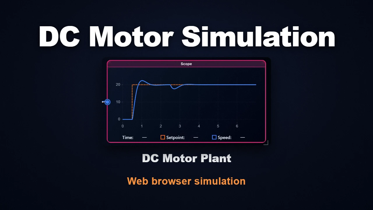
Velocity Step Response and Load Rejection
Simulating a 12V DC motor accelerating to (), followed by a load step at showing speed sag and armature current ramp to .
Closed-Loop PID Servo Position Control
Connecting the DCMotor in thirdOrder mode to a PIDController for angular position regulation (), achieving critically damped settling within .
Remarks & Best Practices
- Numerical Stability: Default parameters yield balanced time constants (, ), well-conditioned for explicit integration.
- Port Flexibility: The
loadTorqueinput defaults to zero if unconnected.
Frequently Asked Questions (FAQ)
Q: Why does my DC Motor simulation oscillate or become unstable with very small inductance L?
When the electrical time constant is significantly smaller than the simulation step size (), the differential equation for armature current becomes numerically stiff. If you wish to neglect inductance without changing the simulation step size, select 1st Order in the dynamicsMode dropdown or set . The block will automatically switch to an exact algebraic calculation of armature current , guaranteeing numerical stability.
Related Components
- PIDController" class="bw-link">PIDController
- SecondOrderSystem" class="bw-link">SecondOrderSystem
- StateSpace" class="bw-link">StateSpace
- TransferFunction" class="bw-link">TransferFunction